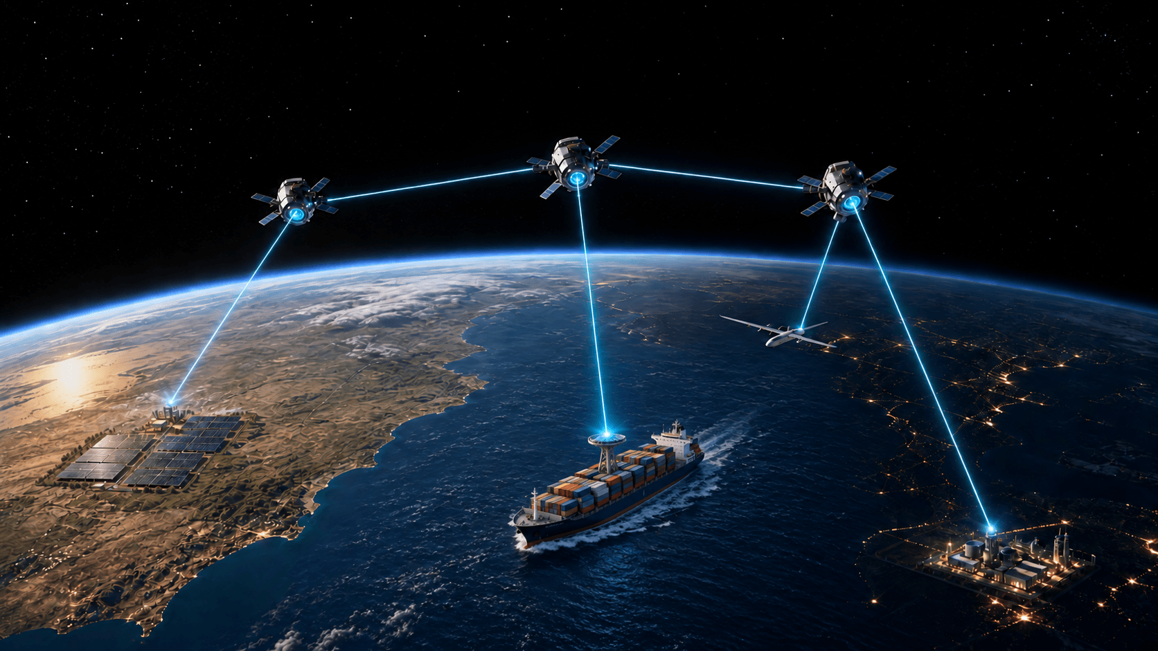
Concept of a laser power network connecting ground generation to ships, aircraft, and ground demand through low-Earth-orbit relays

TECHNOLOGY / LASER POWER NETWORK

POWER,
ROUTED BY LASER.

Connect regions with surplus generation to regions with power shortages through a laser network in low Earth orbit. As generation and demand change, the network allocates power from multiple sources to multiple destinations.

CONCEPT VISUAL

THE COMPLETE POWER PATH

THREE SYSTEMS.
ONE LOSS BUDGET.

A laser source alone is not a power network. Electricity must become a high-output, high-efficiency, high-beam-quality CW laser; many changing sources and destinations must be connected through orbit; and the laser must become useful electrical power at the receiver. All three boundaries must work together.

01

ELECTRICITY → LASER

SOURCE CONVERSION

Deliver high output, high wall-plug efficiency (WPE), and high beam quality at the same CW operating point. Compare single-source scaling, independent-beam power addition, spectral combining, and coherent combining—including thermal limits, combining loss, sidelobes, and fault isolation.
HIGH OUTPUTHIGH WPEHIGH BEAM QUALITY
02

N SOURCES → N DESTINATIONS

REAL-TIME OPTICAL ROUTING

Generation, demand, satellite position, and path state change every second. Relay the main power as laser beams while acquisition, tracking, wavefront control, power allocation, and handover operate as one control system.

PATOPTICAL-THROUGH RELAYDYNAMIC N×N
03

LASER → USEFUL POWER

RECEIVER CONVERSION

Co-design wavelength-matched photovoltaic conversion, illumination, temperature, maximum-power-point tracking, and power electronics. Measure continuous useful output from the receiving aperture to the customer load—not a record from an isolated cell.

PHOTOVOLTAIC CONVERSIONTHERMALPOWER ELECTRONICS
≥70%LONG-TERM END-TO-END TARGET

Measured from AC input at the generation site to AC output at the demand site. This is neither a demonstrated result nor the best efficiency of an isolated component; it is the design target that constrains every loss in the system.

FIRST DEMONSTRATION / ELECTRIC SHIPS

POWER AT SEA.
MORE RANGE.

We will begin with electric ships: receive laser power onboard and turn it into electricity for propulsion and ship systems. The aim is to extend range without carrying all voyage energy in batteries, preserving space for cargo.

01

SEAWATER COOLING

A separate coolant loop can move receiver heat through a heat exchanger into seawater. This gives the ship a practical route for rejecting heat while we develop the receiver.

02

ROOM TO BUILD

Larger vessels offer room for receiver apertures, cooling equipment, and instrumentation. We can develop the integrated hardware before reducing its mass for flight.

03

POWER IN MOTION

Sea trials bring beam tracking, conversion, and shipboard electrical loads together. Measure useful output while the vessel moves, then apply what we learn to aircraft and ground receivers.

Onboard batteries cover weather interruptions, route handovers, and reserve. Receiver size, cooling capacity, and tracking must be designed together for the vessel.

AVIATION / LASER POWER IN FLIGHT

FLY ON POWER
FROM ORBIT.

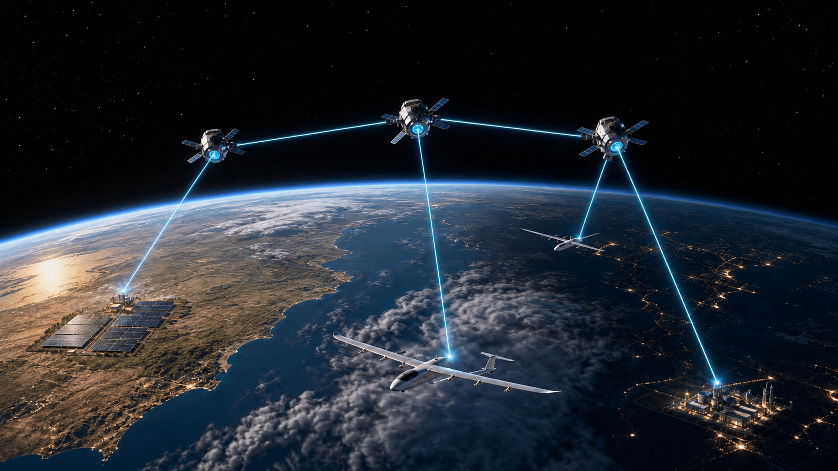
Low-Earth-orbit satellites beam laser power to electric aircraft in flight. A receiver onboard converts the light into electricity to drive the motors during cruise.

Receiving power in flight reduces the battery mass needed to store cruise energy, making the aircraft lighter.

OPERATING COST

1/3

Total operating cost compared with conventional fuel aircraft

Company estimate at 70% end-to-end efficiency.

01

ABOVE THE CLOUDS

Delivering power from orbit to aircraft above the clouds avoids cloud layers that would block a beam from the ground.

02

TRACK THE RECEIVER

Keep the laser aligned with the moving aircraft receiver. Stop transmission whenever safe alignment cannot be maintained.

03

BATTERY BACKUP

Acquire the next route before switching. Onboard batteries cover takeoff, landing, satellite handovers, interruptions, and reserve.

01 / LASER SOURCE

THREE CONSTRAINTS.
ONE CW OPERATING POINT.

Separate records for high output, high WPE, and high beam quality do not add up to a viable power-beaming source. We measure all three at the same CW operating point and extend the loss boundary through drivers, thermal control, beam combining, and transmit optics.

HIGH CW OUTPUT

Useful optical output sustained under steady-state thermal conditions during continuous-wave operation—not a peak or short-pulse value.

HIGH WALL-PLUG EFFICIENCY

Laser output divided by electrical input to the laser device, distinguished from slope efficiency, optical-to-optical efficiency, and full source-system efficiency including power supplies and thermal control.

HIGH BEAM QUALITY

Connect M², beam parameter product, far-field intensity, and encircled energy to transmit and receive apertures and the required capture fraction.

THERMAL & RELIABILITY

Junction temperature, optical-surface damage, wavelength and phase drift, sustained operation, and isolation of failed channels.

PATH A

SINGLE-SOURCE SCALING

Scale a single laser architecture such as a PCSEL while retaining high beam quality and WPE.

PATH B

ARRAYED SOURCES

Distinguish independent beams added at the receiver, spectral beam combining, and coherent beam combining; compare beam quality, phase, wavelength, thermal crosstalk, combining loss, and sidelobes.

02 / DYNAMIC N×N ROUTING

DEMAND CHANGES.
THE PATH CHANGES.

When moving surplus generation from high-insolation regions such as Nevada and Arizona to cities, factories, and data centers, a fixed point-to-point link is insufficient. Inputs, outputs, routes, and allocation must be continuously reconfigured.

This is not a packet network that stores power at intermediate nodes. It is an optical circuit-switched network that establishes a simultaneous laser path from source to destination. N×N does not mean copying one beam: multiple independent beams and optical ports are actively pointed, with channel count and source output adjusted to allocate power.

SOURCE ASOURCE BSOURCE N
LEO OPTICAL MESHN×NPATH + POWER ALLOCATION
CITYINDUSTRYSHIPAIRCRAFT
  1. 01

    STATE ESTIMATION

    Update generation, demand, satellite position, terminal state, cloud and atmospheric conditions, and thermal margin.

  2. 02

    PATH & POWER ALLOCATION

    Compare loss and capacity across multiple paths, then allocate output to each destination in real time.

  3. 03

    MAKE-BEFORE-BREAK

    Acquire the next path first; switch satellites or receivers only after optical closure and safe-state confirmation.

  4. 04

    FAULT & SAFETY CONTROL

    Detect tracking excursions, optical contamination, overheating, or intrusion into protected airspace and beam paths; isolate, reallocate, or shut down safely.

OPTICAL-THROUGH RELAY

KEEP THE MAIN POWER
IN THE LASER PATH.

Converting the received laser to electricity at every relay and using it to drive another laser would compound conversion loss and heat at every hop. The main transmitted energy remains in the laser path and is optically redirected to the next satellite, ship, ground receiver, or aircraft.

RECEIVE
TELESCOPE
→COARSE
POINTING
→WAVEFRONT
CONTROL
→FAST-STEERING
MIRROR
→TRANSMIT
TELESCOPE

POINTING, ACQUISITION & TRACKING

Integrate beacons, point-ahead, attitude estimation, coarse pointing, and fast fine-angle correction to hold the beam on a moving downstream aperture.

TRUE STAGE EFFICIENCY

Stage efficiency is the useful-mode power captured at the next receive aperture divided by the laser power sent toward a relay. It includes diffraction, wavefront error, pointing error, and capture fraction—not mirror reflectivity alone. Ninety percent is the rejection floor for a candidate relay; the design value needed for ≥70% end to end must be back-solved from endpoint efficiencies and hop count.

DESIGN SENSITIVITY / 96–99% CLASS MAY BE REQUIRED / NOT DEMONSTRATED

03 / RECEIVER

TURN THE LASER
BACK INTO POWER.

The receiver is not a conventional solar panel placed in the beam. We co-optimize a photovoltaic power converter (PPC) matched to the selected laser wavelength and irradiance, receive optics, power electronics, and thermal design.

WAVELENGTH MATCH

Match laser center wavelength and spectral width to the receiver cell bandgap and spectral response.

ILLUMINATION MAP

Measure efficiency and temperature under nonuniform illumination, incidence-angle changes, tracking error, and local hot spots.

CELL & ARRAY ELECTRICAL DESIGN

Preserve useful output through series-resistance control, cell segmentation, series-parallel topology, bypassing, and failed-cell isolation.

MPPT & POWER CONDITIONING

Track the maximum power point under changing laser input, then connect to the load through DC/DC conversion and an inverter.

NET RECEIVER EFFICIENCY

Measure a single boundary from laser input at the receive aperture to load-side output after subtracting cooling and control auxiliaries.

Concept of laser power delivery from low Earth orbit to an electric aircraft in cruiseCONCEPT VISUAL

BUILD THIS NETWORK

ONE HARD SYSTEM
IS ENOUGH.

Laser sources, optical relays, PAT, dynamic routing, receivers, power electronics, thermal engineering, and safety: we want to speak directly with people who have built hardware in any one of these domains.

REQUEST A TECHNICAL INTERVIEW ↗